Contrl Wiring Diagram Of Star Delta Starter - Star Delta Starter Wiring Diagram : R , y, b = red, yellow, blue ( 3 phase lines)c.b = general circuit breakermain = mai supplyy = starδ = deltac1, c2, c3 = contatcors (power diagram)o/l = over load relayno = normally opennc = normally closed k1 = contactor (contactor coil) k1/no = contactor holding coil.
byAdmin-
0
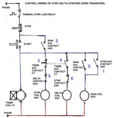
Contrl Wiring Diagram Of Star Delta Starter - Star Delta Starter Wiring Diagram : R , y, b = red, yellow, blue ( 3 phase lines)c.b = general circuit breakermain = mai supplyy = starδ = deltac1, c2, c3 = contatcors (power diagram)o/l = over load relayno = normally opennc = normally closed k1 = contactor (contactor coil) k1/no = contactor holding coil.. If the motor is too heavily loaded, there will not for star delta starter circuit diagram,wiring technique and motor base termination,please read my post for star delta… The on delay timer diagram is also shown in the diagram. Star delta starter control circuit wiring diagram consist timer, push button for start and stop. In the above star delta starter control circuit wiring diagram with timer and normally close push buttonnormally open push button switch. Star delta starter wiring diagram manual timer connection working starters explained the motor plc to agriculture complying latest programming and how avoid failure automatic 3te7291 0a amp 20 hp electronic 32 siemens three phase pgfa 2 air compressor guide apps on electro mechanical dol control panel deekay electricals soft 3rw44 typical.
15 star delta starter control circuit diagram. A 8 pin timer is used. The following section of plc tutorial will explain the ladder programming for star delta motor starter. Next, the circuit goes through the nc terminals of the thermal over load relay. Star delta starter control diagram | star delta control wiring | control diagram |star delta hindi#stardeltacontrolcircuit #controlcircuithiii, i am aayus.
Electrical Revolution Control Circuit Of Semi Automatic Star Delta Starter from 1.bp.blogspot.com Here you can see the control circuit diagram of automatic star delta starter. Connect a thermal overload relay with the main contactor as shown in the above diagram. In the above star delta starter control circuit wiring diagram with timer and normally close push button/normally open push button switch. A 8 pin timer are used. As shown in the fig. A 8 pin timer is used. Wiring diagram star delta schneider. Connect those all terminal with the motor as shown in the above diagram.
Most induction motors are started directly on line, but when very large motors are started that way, they cause a disturbance of voltage on the supply lines due to large starting curr…
Star delta starter control circuit wiring diagram consist timer, push button for start and stop. The following section of plc tutorial will explain the ladder programming for star delta motor starter. Star delta starter wiring diagram, this post is about the main wiring connection of three phase motor with star delta starter and control wiring diagram of 1 mccb circuit breaker 3 magnetic contactors 3 phase motor thermal overload relay / electronic overload relay ocr an on daily timer (8 pin timer. Star delta starters consist of a power circuit and control circuit. If the motor is too heavily loaded, there will not for star delta starter circuit diagram,wiring technique and motor base termination,please read my post for star delta… As shown in the fig. Star delta starter wiring diagram manual timer connection working starters explained the motor plc to agriculture complying latest programming and how avoid failure automatic 3te7291 0a amp 20 hp electronic 32 siemens three phase pgfa 2 air compressor guide apps on electro mechanical dol control panel deekay electricals soft 3rw44 typical. A 8 pin timer is used. Most induction motors are started directly on line, but when very large motors are started that way, they cause a disturbance of voltage on the supply lines due to large starting curr… Star delta starter control wiring. A star delta starter is the most commonly used method for the starting of a 3 phase induction motor. Star delta starters explained the engineering mindset. The control circuit uses to control the starter circuit such as on, off and tripping operations.
This energized star contactor coil and motor get connected in star. And also i will explain this starter connection step by ste. A 8 pin timer are used. In star delta starting an induction motor is connected i. Refer to the below star delta circuit,
Download Learn Star Delta Wiring Diagram On Pc Mac With Appkiwi Apk Downloader from lh3.googleusercontent.com Most induction motors are started directly on line, but when very large motors are started that way, they cause a disturbance of voltage on the supply lines due to large starting curr… A 8 pin timer is used. The on delay timer diagram is also shown in the diagram. And also i will explain this starter connection step by ste. And their applications with advantages. As shown in the fig. Star delta starter control diagram | star delta control wiring | control diagram |star delta hindi#stardeltacontrolcircuit #controlcircuithiii, i am aayus. A 8 pin timer are used.
In the above star delta starter control circuit wiring diagram with timer and normally close push button/normally open push button switch.
This energized star contactor coil and motor get connected in star. Connect those all terminal with the motor as shown in the above diagram. In this tutorial we will show the star delta y d 3 phase induction ac motor starting method by automatic star delta starter with timer with schematic power control and wiring diagram as well as how star delta starter works and their applications with advantages and disadvantages. A star delta starter is the most commonly used method for the starting of a 3 phase induction motor. As you see in the above star delta starter diagram, first, an nc push button switch is connected to stop the operation. Most induction motors are started directly on line, but when very large motors are started that way, they cause a disturbance of voltage on the supply lines due to large starting curr… Star delta starter control circuit diagram. Star delta starter control wiring. The on delay timer diagram is also shown in the diagram. Star delta connection circuit diagram: Refer to the below star delta circuit, If the motor is too heavily loaded, there will not for star delta starter circuit diagram,wiring technique and motor base termination,please read my post for star delta… The following section of plc tutorial will explain the ladder programming for star delta motor starter.
Motor control panel wiring diagram pdf star delta starter electrical notes articles is one of the pictures that are related to the picture before in the collection gallery, uploaded by autocardesign.org.you can also look for some pictures that related to wiring diagram by scroll down to collection on below this picture. If you want to find the other picture or article about motor control panel. A star delta starter is the most commonly used method for the starting of a 3 phase induction motor. If the motor is too heavily loaded, there will not for star delta starter circuit diagram,wiring technique and motor base termination,please read my post for star delta… Here you can see the control circuit diagram of automatic star delta starter.
Star Delta Wiring Diagram Free Download And Software Reviews Cnet Download from download.cnet.com As shown in the fig. Wiring diagram star delta schneider. Star delta starter control circuit diagram. And also i will explain this starter connection step by ste. Most induction motors are started directly on line, but when very large motors are started that way, they cause a disturbance of voltage on the supply lines due to large starting curr… Star delta starters explained the engineering mindset. Star delta starter wiring diagram, this post is about the main wiring connection of three phase motor with star delta starter and control wiring diagram of 1 mccb circuit breaker 3 magnetic contactors 3 phase motor thermal overload relay / electronic overload relay ocr an on daily timer (8 pin timer. One is power circuit and another one is control circuit.
Here you can see the control circuit diagram of automatic star delta starter.
If you want to find the other picture or article about motor control panel. Star delta starters explained the engineering mindset. Motor control panel wiring diagram pdf star delta starter electrical notes articles is one of the pictures that are related to the picture before in the collection gallery, uploaded by autocardesign.org.you can also look for some pictures that related to wiring diagram by scroll down to collection on below this picture. In the above star delta starter control circuit wiring diagram with timer and normally close push button/normally open push button switch. The on delay timer diagram is also shown in the diagram. Dosto aaj ki is video me aap dekheenge star delta starter control circuit diagram or kaise kaam karta hai #stardeltastartercircuitsubscribe yk electrical for. In the above star delta starter control circuit wiring diagram with timer and normally close push buttonnormally open push button switch. Now, you have a total of six terminals to connect with the motor three from the output of the olr and three from the output of the delta contactor. Star delta starter wiring diagram manual timer connection working starters explained the motor plc to agriculture complying latest programming and how avoid failure automatic 3te7291 0a amp 20 hp electronic 32 siemens three phase pgfa 2 air compressor guide apps on electro mechanical dol control panel deekay electricals soft 3rw44 typical. In star delta starting an induction motor is connected i. A star delta starter is the most commonly used method for the starting of a 3 phase induction motor. The control circuit uses to control the starter circuit such as on, off and tripping operations. Most induction motors are started directly on line, but when very large motors are started that way, they cause a disturbance of voltage on the supply lines due to large starting curr…